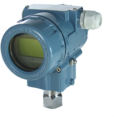
BXY6002 Gage Pressure Transmitter
BXY6003- Absolute Pressure Transmitter
The BXY6002/3-gauge/absolute pressure transmitter is used to measure the liquid level, density, and pressure of liquids, gases, or vapors, and then convert them into 4-20mADC HART current signals for output. BXY6002/3 can also communicate with RST375 handheld terminals or RSM100 Modems for parameter setting, process monitoring, etc.
Standard specifications
(Calibrate the range based on the standard zero point, stainless steel 316L diaphragm, filled with silicone oil)
1 Performance specifications
Reference accuracy for range adjustment
(Including linearity, backlash, and repeatability from zero)
± 0.075%
If TD>10 (TD=maximum range/adjustment range), then it is:
± (0.0075 × TD)%
Environmental temperature impact
|
Range code
|
-Total impact from 20 ℃ to 65 ℃
|
|
B/L
|
±(0.30×TD+0.20)%×Span
|
|
other
|
±(0.20×TD+0.10)%×Span
|
|
Range code
|
-40℃~-20℃和65℃~85℃
Total impact amount
|
|
B/L
|
±(0.30×TD+0.20)%×Span
|
|
other
|
±(0.20×TD+0.10)%×Span
|
Over range impact: ± 0.075% × Span
Long term stability
|
Range code
|
influence quantity
|
|
B/L
|
±0.2%×Span/1year
|
|
other
|
±0.1%×Span/1year
|
Power impact
± 0.001%/10V (12-42V DC), negligible
2 Functional specifications
Range and range (BXY6002 gauge pressure)
|
Range/Range
|
kPa
|
bar
|
|
B
|
range
|
0.6~6
|
6~60mbar
|
|
range
|
-6~6
|
-60~60mbar
|
|
C
|
range
|
2~40
|
0.02~0.4
|
|
range
|
-40~40
|
-0.4~0.4
|
|
D
|
range
|
2.5~250
|
0.025~2.5
|
|
range
|
-100~250
|
-1~2.5
|
|
F
|
range
|
30~3000
|
0.3~30
|
|
range
|
-100~3000
|
-1~30
|
|
G
|
range
|
0.1~10MPa
|
1~100
|
|
range
|
-0.1~10MPa
|
-1~100
|
|
H
|
range
|
0.21~21 MPa
|
2.1~210
|
|
range
|
-0.1~21 MPa
|
-1~210
|
|
I
|
range
|
0.4~40 MPa
|
4~400
|
|
range
|
-0.1~40 MPa
|
-1~400
|
|
J
|
range
|
0.6~60 MPa
|
6~600
|
|
range
|
-0.1~60 MPa
|
-1~600
|
Range and Range (BXY6003- Absolute Pressure)
|
Range and Range
|
kPa
|
bar
|
|
L
|
Range
|
2~40
|
0.02~0.4
|
|
Range
|
0~40
|
0~0.4
|
|
M
|
Range
|
2.5~250
|
0.025~2.5
|
|
Range
|
0~250
|
0~2.5
|
|
O
|
Range
|
30~3000
|
0.3~30
|
|
Range
|
0~3000
|
0~30
|
Range limit
Within the upper and lower limits of the range, it can be adjusted arbitrarily. It is recommended to select range codes with the lowest possible range ratio to optimize performance characteristics.
Zero point setting
The zero point and range can be adjusted to any value within the measurement range in the table, as long as the calibrated range is ≥ the minimum range
Installation position impact
The change in installation position parallel to the film surface will not cause zero drift. If the installation position changes by more than 90 ° to the film surface, there will be zero drift within the range of<0.25kPa for range C, and zero drift within the range of<0.15kPa for other ranges. All can be corrected by adjusting zero. No range impact.
Output
2-wire system, 4-20mADC, selectable for digital communication with HART output, with options for linear or square root output.
Output signal limit: Imin=3.9mA, Imax=20.mA
Alarm current
Low alarm mode (minimum): 3.7 mA
High alarm mode (maximum): 21 mA
No alarm mode (hold): maintain the effective current value before the fault
Alarm current standard setting: high alarm mode
Response time
The damping constant of the amplifier component is 0.1s; The sensor time constant is between 0.1 and 1.6 seconds, depending on the range and range ratio. The additional adjustable time constant is 0.1~60s.
Preheating time:<15s
Environmental temperature
-40-85 ℃
When equipped with LCD display and fluororubber sealing ring, -20~65 ℃
Storage temperature/transportation temperature
-50-85 ℃
With LCD display: -40~85 ℃
Pressure limit
From vacuum to maximum range.
Overload limit:
|
Range
|
6kPa
(B)
|
40kPa
(C/L)
|
250kPa
(D/M)
|
3MPa
(F/O)
|
|
Overload limit
|
0.2MPa
|
1MPa
|
4MPa
|
16MPa
|
|
Range
|
10MPa
(G)
|
21MPa
(H)
|
40MPa
(I)
|
60MPa
(K)
|
|
Overload limit
|
20MPa
|
50MPa
|
50MPa
|
70MPa
|
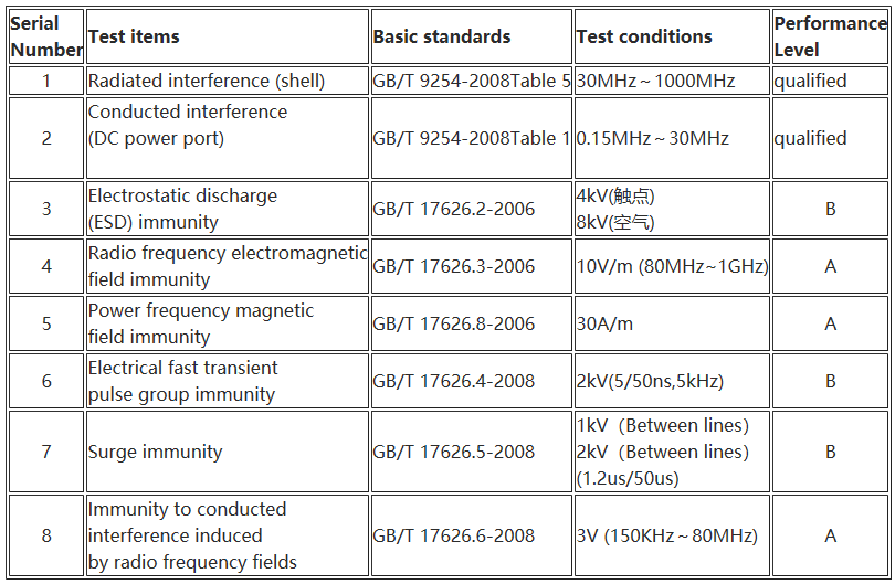
Electromagnetic compatibility (EMC)
Refer to the "Electromagnetic Compatibility Schedule" on the next page
3 Installation
Power supply and load conditions
The power supply voltage is 24V, R ≤ (Us-12V)/Imax k Ω
Where Imax=23 mA
Maximum power supply voltage: 42VDC
Minimum power supply voltage: 12VDC, 15VDC (backlight LCD display)
Digital communication load range: 230~600 Ω
Electrical connections
M20X1.5 cable sealing buckle and wiring terminal are suitable for wires ranging from 0.5 to 2.5mm2.
Process Connection
Standard process connection: NPT 1/2 internal thread, can be converted into NPT 1/2, G1/2, and M20x1.5 external thread, KF16 vacuum interface.
4 Physical specifications
material quality
Diaphragm: stainless steel 316L, Hastelloy C
Process connection: stainless steel 316L
Filling fluid: silicone oil
Transmitter housing: aluminum alloy material, with epoxy resin sprayed on the surface
Shell sealing ring: nitrile rubber (NBR)
Nameplate: stainless steel 304
Weight
1.6kg (without LCD display, mounting bracket, process connection)
Shell protection level
IP67
Electromagnetic Compatibility Schedule
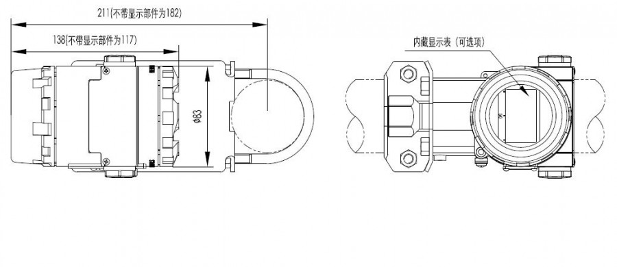
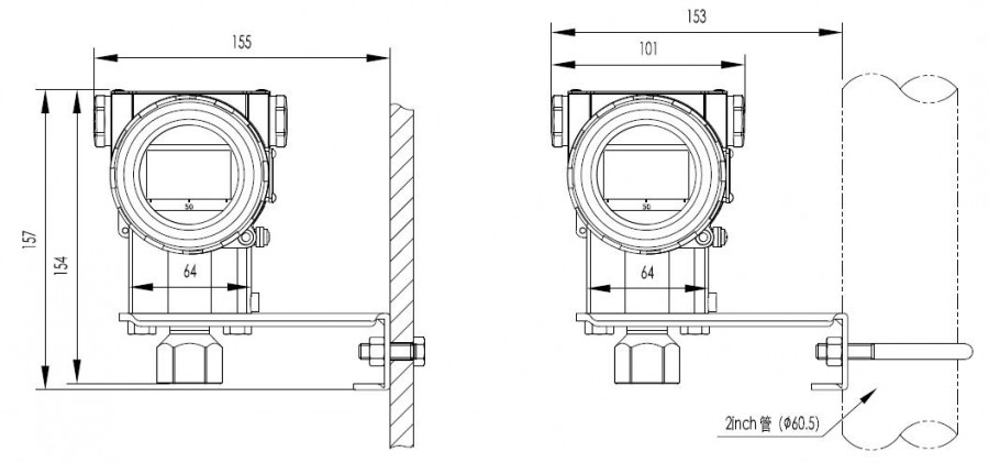
External dimension unit (mm)
Horizontal piping connection method (side) Horizontal piping connection method (front)
Wall mounted connection method Vertical piping connection method
5 Electrical connection diagram
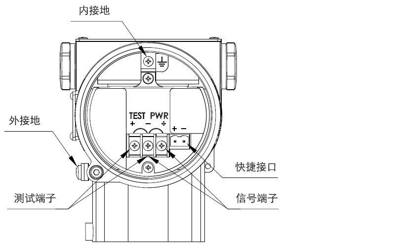
Note: The quick interface function is equivalent to the signal terminal.
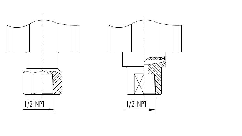
6 Process Connection Instructions (Code 1)
6.1 Standard Form (Code 1)
D/M/F/G/H/I/K/O Range Interface Diagram B/C/L Range Interface Diagram
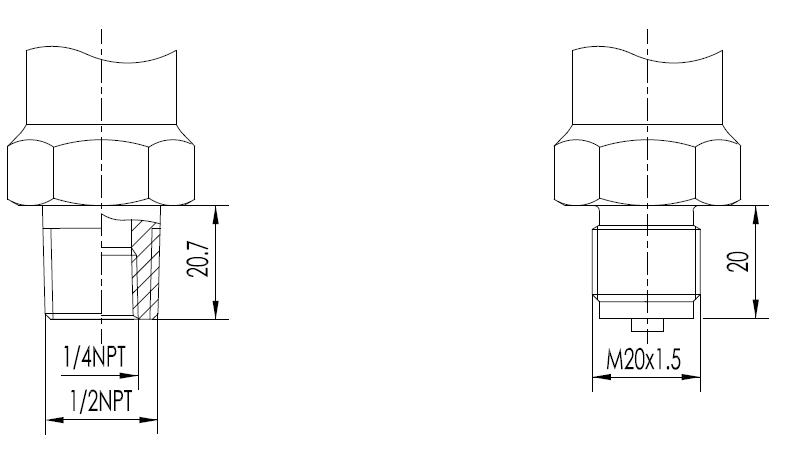
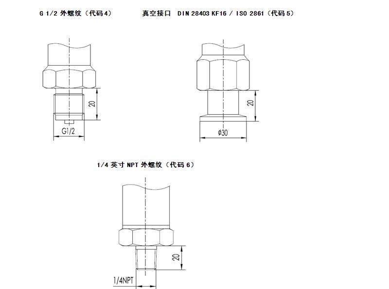
6.2 Derived interface form
1/2 inch NPT external thread (code 2) M20x1.5 external thread (code 3)
| 